3D printing of spare parts is a very good option for components, for which production is no longer available. The production of a spare part is a very cost-intensive and time-consuming process if made with the traditional methods. Additive manufacturing is worthwhile in such cases, even for private persons. In another blog post, we reported for spare parts for vintage speakers, that we printed for private persons.
Often there are no existing design drawings in order to get to 3D printing at all. In this case, the spare part must first be exactly replicated. This is called reverse engineering. There are two ways to create a 3D model of a part: either the original part is scanned and a 3D model is derived, or the 3D model is created using a CAD tool.
Scanning an object is cost-intensive because professional 3D scanners are quite expensive. It is the best solution for objects with complex geometries. Manual component design, on the other hand, is a very reliable method for smaller objects with simple geometry. In this process, the objects are precisely measured and reproduced with a CAD tool.
Fig. Ring clamp for mounting an LED spotlight
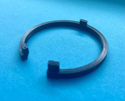
We show here how this process works with a concrete example. We have chosen a ring clamp with three hooks for mounting LED spotlights. With the original ring clamp, the plastic has become very hard over time under the constant temperature load and breaks easily when the lamp needs to be replaced. In addition, due to the lost elasticity of the clamp, the LED spotlight always pops out. We also want to print the part from ASA, as this filament is stable and at the same time very resistant to heat and UV radiation.
Step 1: We measure the component precisely with the help of a caliper gauge
Step 2: We create a 3D model with a CAD tool
If necessary, we change the construction geometry of the part so that we can ensure better printability and if possible without a support construction.
The ring clamp has three hooks. In the original part, the profile of the hook looks like this in cross-section:
There is a 90° overhang in this geometry. 3D printing 90° overhangs requires a support construction. To avoid this, we are left with two options:
Variant 1:
We can change the geometry in the heel area to a solid object without losing functionality, so there is no overhang.
Variant 2:
We change the existing building geometry so that a greater than 45° linear overhang is created. Overhangs greater than 40°- 45° can be printed cleanly by our printers.
The intelligent solution in this case is variant 2, because it saves material and printing time. There is no need to remove a support structure, which means there are no visible marks on the surface.
Fig. Reproduction of the spare part using a CAD tool (FreeCad). The construction geometry of the original ring clamp was slightly modified and optimised for 3D printing.
Step 3: The part is printed
Fig. The 3D-printed spare parts from ASA filament has a longer service life compared to the original part
For relatively simple parts, manual design is often the fastest and most cost-effective solution. Measuring, creating the part with the CAD tool and then 3D printing took a total of just 1 hour. And we were able to achieve a lot in the process:
- We optimised the geometry without losing the functionalities of the original part.
- We have printed the part from a material that is suitable for the case and thus we have improved the service life of the original part.
- If needed, the part can be replicated again and again with additive manufacturing
Using reverse engineering, we can produce a 3D model and an exact replica using an available old part. LVtech can help you adapt the part so that the new part has even better properties with the same functionalities.


